iAMP100
iAMP100-MOSFET

VSHA

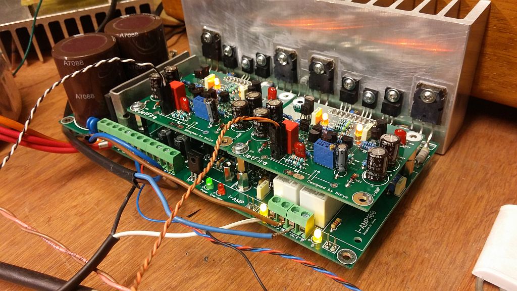
JetFire
Cliffjumper

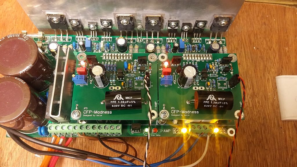
CFP-Madness
A9
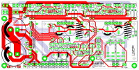
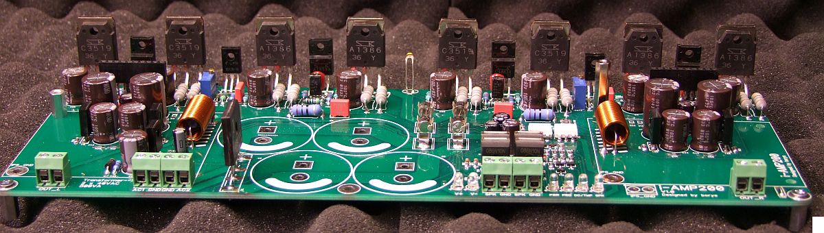
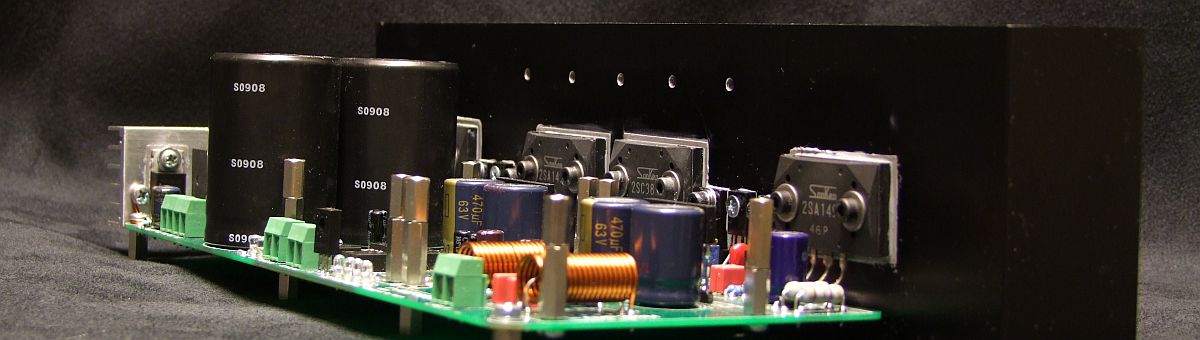
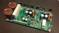
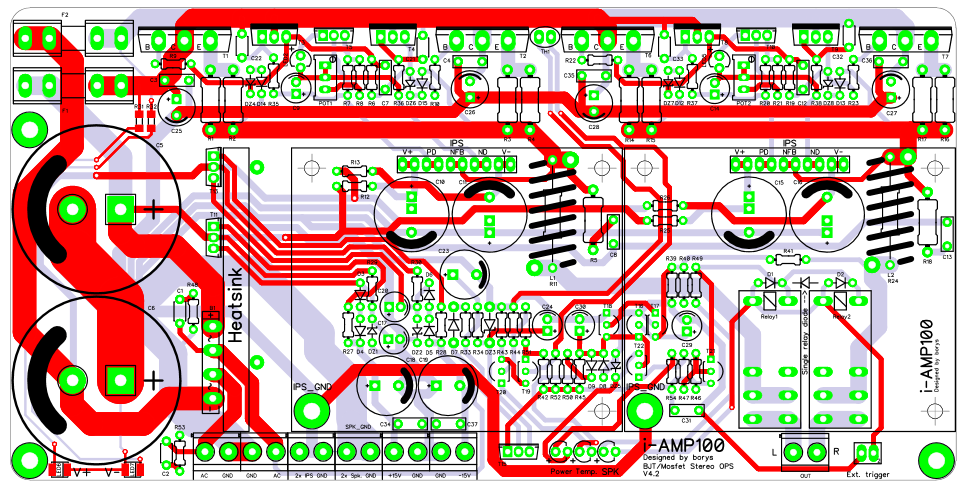
iAMP100 V4.2 PCB
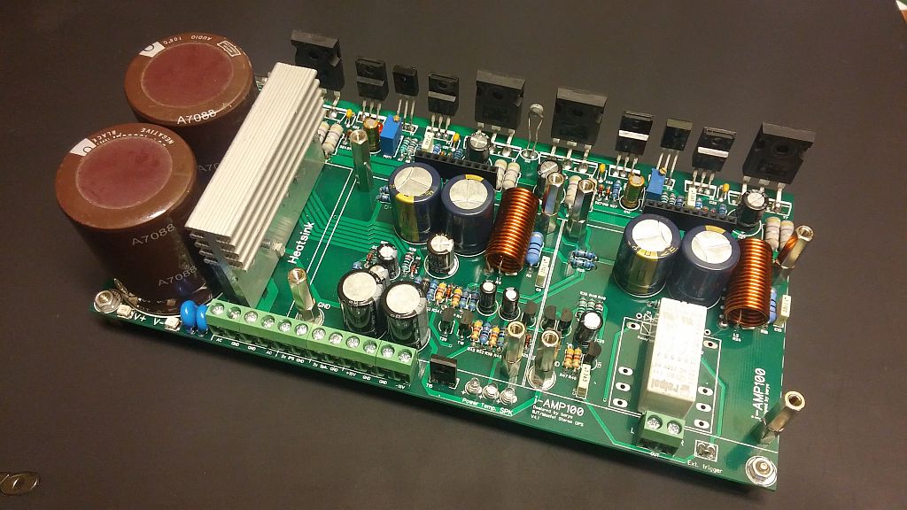

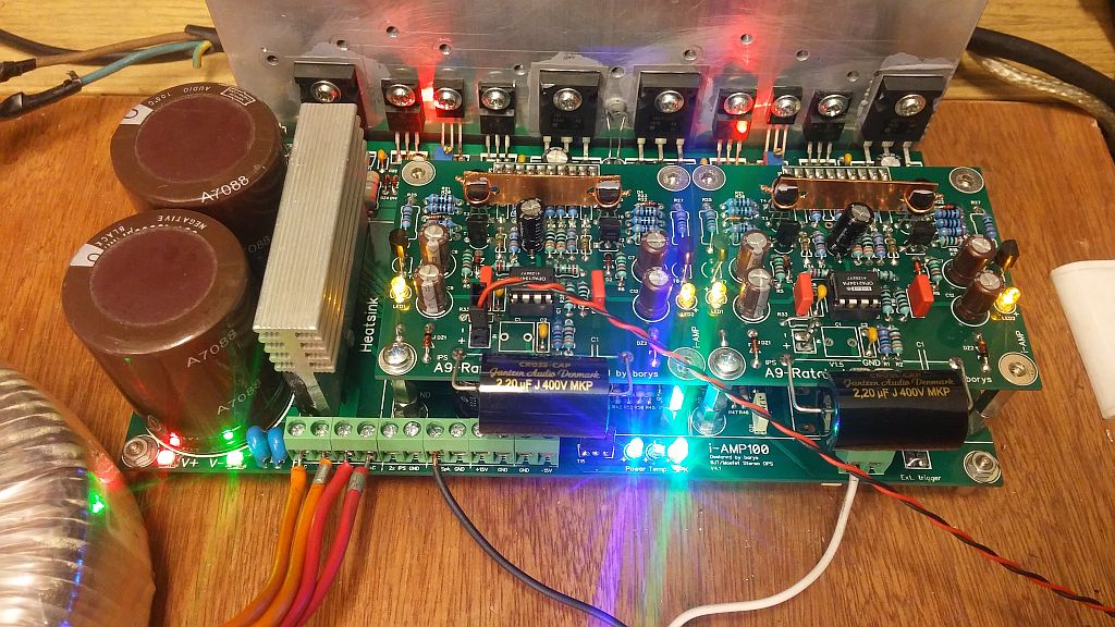
iAMP100 is a basic, the simplest version of the stereo OPS unit I have made.
The main board consists:
- BJT double emiter follower output stage / MOSFET source follower output stage (depend on the schematic)
- +/- 15V @ 100mA power supply unit (short circuit protected)
- Thermal protection
- DC protection
- Fast speakres OFF feature
- Delayed speakers ON feature - reduces speakers ''thumb'' at amplifier turning ON phase
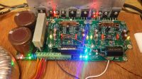
- LED diagnostics
The main board requires 2x 28Vac transformer to support 4R load and max 2x 32Vac transformer for 8R load support (max 2x 35Vac tranformer).
The transformer size can be matched to the requirements so the rail voltage will drop respectively to the load and the output power will be reduced.
The higher the load (lower impedance) the larger rail voltage drop and lower output power.
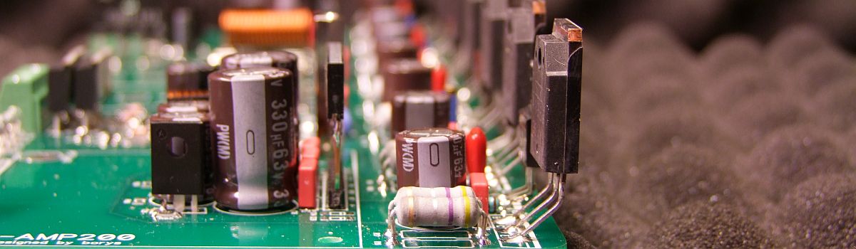
All the components on the board are standard and available in the closest electronics store.
MOSFET OUTPUT STAGE:
BJT output tranisistors are used very often and they are well documented so I will focus on the ''MOSFET'' side of the amplifier.
For MOSFET output stage a few changes have to be made:
-solder gate protection diodes
-change resistor values in Vbe generator and gate ''stoppers''
-solder RED LED in the Vbe circuit ( LED must be replaced with a jumper in BJT version!! )
With this simple Vbe generator the output devices bias is over-compensated approx 10-15% in mostly used by DIYers ''free air'' amplifier aplication.
After amplifier board is placed inside enclosure the temperature compensation of the whole amplifier may change a bit.
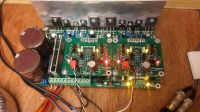
I have used two types of the mosfets, the first pair is IRFP240/9140, it is well matched N-chanel & P-chanel pair but it can be used only up to +/-50V at the main rails (above +/- 50V use IRFP9240 instead IRFP9140).
The second type of the mosfets are the same as in top SONY ES amplifiers, the famous 2SJ201/2SK1530 with 2Sj313/2SK2013 drivers. I must say this is my favourite combination !!
A few yeares back I have traded a bag of gold for them and than I left them in the drawer. Now I must build a time machine to come back and buy a few more :D
They fitt in my ''sound'' preferences perfectly, highly recommended.
PROTECTION CIRCUIT
Protection circuit is simple (as whole amplifier is), the only rocket science in it is a Schmitt trigger, very widely used in automation in temperature controll circuits.
Shmitt trigger provides a bit of the histeresis required for Temperature protection.
DC protection circuit provides speakers delay after amplifer is turned ON, time contstant is setted by the RC network (R45=1Meg and C30=10uF) so it is very easy to change it by replacing C30 capacitor with differend value one.
Speaker terminals are switched ON/OFF by the 24V/1,44kR relays. Board layout allows to use single or two separate relays (depending on stock parats).
AUXILARY +/-15V@100mA PSU
For a safety reasons the auxilary PSU output current is limited to 100mA per rail, the limiting factor is a heat dissapation of the line regulator transistors
Why the circuit is so basic and simple ?
-it is very easy to build it for a beginners
-low cost of the materials
-short circuit protection / current liimt
-if a better voltage regulation is required the local/cascoded (at the preamplifier board) voltage stabilisation is needed anyway (as close as possible to the output/input ciruits)
-very easy output voltage setup (just replace DZ1 and DZ2 with different values)